Welcome back to our IoT development journey, where we explore the fascinating world of the Internet of Things (IoT) using the Quectel EC200U Cellular Module, STM32 microcontrollers, and AWS IoT Core. In this chapter, we’re going to dive into the practical side of things and get hands-on with the EC200U module. We’ll guide you through the process of setting up the module, ensuring you have everything in place for effective IoT communication

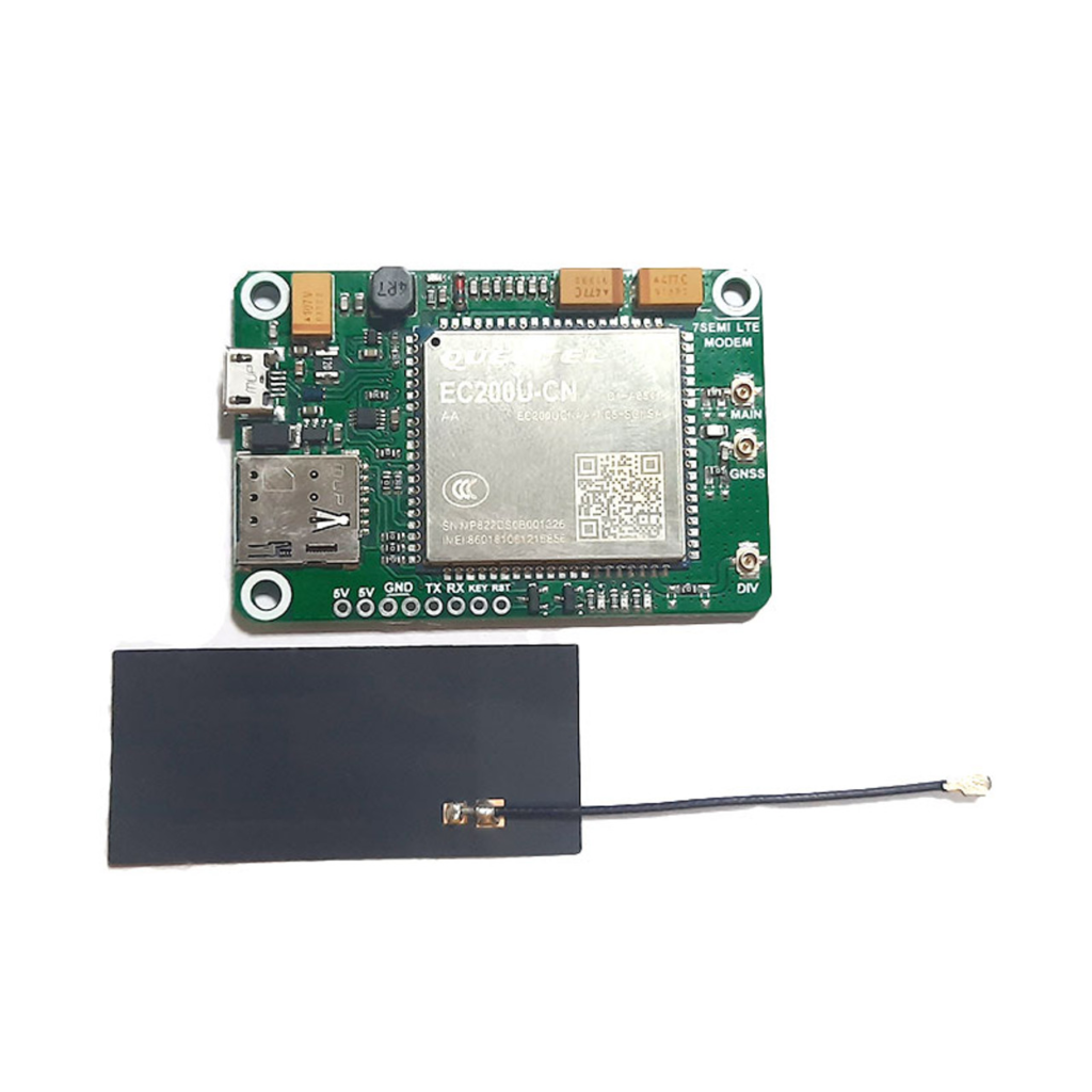
The process will be demonstrated using a specific modem, the 7SEMI LTE 4G Mini Modem, and its associated driver installation. Let’s begin!
Board Specifications:

It’s worth noting that your specific board supports various frequency bands for LTE, including LTE-FDD (B1, B3, B5, B8) and LTE-TDD (B34, B38, B39, B40, B41). Additionally, it offers GSM support at 900MHz and 1800MHz. For positioning and location services, the board is equipped with GNSS capabilities, including GPS, GLONASS, BeiDou, Galileo, and QZSS.
Download the user manual and other tools.
Installing the EC200U-CN USB Modem Driver
The EC200U-CN USB Modem Driver is a critical component for the module’s operation. Follow these steps to install it:
- Download the Driver: Start by downloading the EC200U-CN USB Modem Driver.
- Connect the Modem: Plug your EC200U module into a USB port on your laptop or PC.
- Device Manager: Open the Device Manager. Your module should be detected and visible in the Device Manager.
- Update the Driver: Right-click on one of the “Mobile Generic Serial” entries and choose “Update Driver.”
- Browse for Drivers: Opt for the “Browse my computer for drivers” option.
- Locate Driver Folder: Now, locate the folder “EC200U_quectel_name” and click “Next.”
- Driver Installation: The Quectel USB MOS Port driver should install successfully.
- Repeat for Other Drivers: If there are other drivers to install, repeat the process, ensuring that all drivers are successfully installed.
With the drivers installed, you’re ready to proceed with the EC200U-CN module setup.
Hardware Connections and Considerations
The first step is to ensure you have the necessary hardware and connections in place.
- Power Supply: Make sure you provide a stable power supply to your EC200U module. This board can operate on 5V power either through a USB connection or a 5V serial connection. Verify that your power source is set to the appropriate voltage.
- Antenna Connection: Connect the appropriate antenna securely to the module’s antenna connector. This step is pivotal for efficient signal reception and transmission.
- SIM Card: Ensure a compatible SIM card is correctly inserted. This SIM card is necessary for cellular network access.
Module Communication Verification
Now that you’ve installed the necessary drivers and set up the hardware connections, it’s time to verify if the EC200U module is communicating correctly. This step is vital to ensure that the module can establish a connection with your computer and is ready for further interaction.
Using a USB Cable and Qnavigator Tool
- Connect with USB: Using a USB cable, connect your EC200U module to your computer.
- Open Qnavigator Tool: Launch the Qnavigator tool on your computer.
- Check Communication: After connecting, the Qnavigator tool should detect and recognize the EC200U module. This recognition indicates that your module is communicating correctly with your computer.
UART Communication Using USB-to-TTL
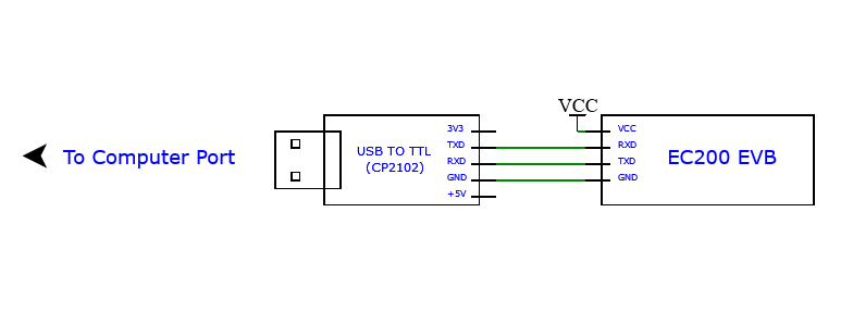
In addition to USB communication, it’s crucial to establish UART communication between the EC200U module and the USB-to-TTL module. This will allow you to send and receive AT commands and data between the two devices, an essential step for IoT development.
- USB-to-TTL Module: Connect the USB-to-TTL module to your computer using a USB cable. This module acts as a bridge between your computer and the EC200U module.
- UART Pins Connection: Properly connect the UART pins between the EC200U module and the USB-to-TTL module. The exact pinout configuration may vary depending on your hardware, so consult the module’s datasheet or documentation for the correct pin connections.
- Configuration: Set the UART parameters, such as baud rate, data bits, stop bits, and parity settings, to match the communication requirements of the EC200U module.
- Testing AT Commands: Once the UART communication is established, you can send AT commands from your computer to the module to check its responsiveness. AT commands are a standardized set of instructions used for controlling modems and other communication devices. By sending AT commands, you can test various functions of the module and verify its proper operation.

With successful communication verification through both USB and UART, you’re well-prepared for the next steps in your IoT development journey. In the upcoming chapter, we’ll delve into STM32 programming. We will explore how to send and receive AT commands between the STM32 board and the EC200U module. Stay tuned, as we take a deeper dive into IoT development and coding with STM32.
Stay connected, and let’s continue building incredible IoT solutions!


Leave a comment